Calibration
of a Photometric Cloud Condensation Nucleus Counter
Designed for Deployment on a Balloon Package
D.
J. Delene* and T. Deshler
Department of Atmospheric
Sciences, University of Wyoming, Laramie
Revised manuscript submitted to the Journal of Atmospheric and Oceanic
Technology, June 11, 1999.
Corresponding
Author: David J. Delene
NOAA Climate Monitoring and
Diagnostics Lab
R/E/CG1 325 Broadway,
Boulder, CO 80303
Office Phone (303) 497-6189
FAX (303) 497-5590
email ddelene@cmdl.noaa.gov
___________
*Now at the Cooperative Institute for Research in
Environmental Sciences (CIRES), University of Colorado/NOAA, Boulder.
ABSTRACT
The importance of
atmospheric aerosols in understanding global climate changes has renewed
interest in measurements of cloud condensation nuclei (CCN). To obtain high-resolution (125 m) vertical
profiles of CCN number concentration, a balloon-borne instrument was
developed. The instrument deduces the
CCN concentration from measurements of laser light scattered by water droplets
that condense on CCN within a static thermal-gradient diffusion chamber. The amount of light scattering is linearly
proportional to the number of droplets within the diffusion chamber. Correlating the number of droplets within
the sample volume with the amount of light scattered by the droplets provides
the calibration constant relating scattered light to CCN concentration. The calibration was tested by comparisons
between the CCN counter and a condensation nuclei (CN) counter when sampling
monodisperse aerosol larger than the CCN counter’s critical activation
size. The calibration constant depends
on supersaturation and slightly on the size of CCN that activate to form
droplets. For dry NaCl aerosol between
35 and 160 nm, the calibration constant varies by less than 10% at 1%
supersaturation. Calibration on ambient
atmospheric aerosol is similar to calibration on laboratory-generated
polydisperse NaCl aerosol indicating that the laboratory calibration can be
applied to field measurements. The time
required for the activation and growth of droplets within the diffusion chamber
is similar during field and laboratory measurements. Overall, the uncertainty of the calibration constant for the
balloon-borne CCN counter is approximately 10% at 1% supersaturation.
Modification for the balloon-borne
CCN counter.
Cloud condensation nuclei (CCN) have a major influence on the
cloud droplet number concentration and hence the radiative properties of
clouds. Increases in CCN
concentrations, resulting from increased SO2 emissions, has been
suggested as a mechanism which could modify clouds properties sufficiently to
affect global climate (Wigley, 1989; Twomey, 1991). The indirect affect of CCN on climate has started to be incorporated
into global climate models (Meehl et al., 1996; Chuang et al., 1997; Pan et
al., 1998). Pan et al., (1998)
concluded from comparisons of climate models that refining input parameters
might be more important than improving models to minimize uncertainties. CCN measurements are an important link in
relating changes in aerosol concentration to changes in cloud droplet number
concentration (Boucher and Lohmann, 1995; Liu et al., 1996). A balloon-borne CCN counter has been developed
to provide vertical profiles of CCN with a resolution of approximately 125
m. Since measurements obtained with the
CCN counter are to be related to concurrent aerosol measurements instead of
simply monitoring changes in CCN concentration, an accurate calibration of the
CCN counter is critical. The main
objective here is to describe the calibration of the balloon-borne CCN counter
and its influence on the accuracy of field measurements.
Description of the CCN counter.
The balloon-borne CCN counter described here is similar to other
static thermal-gradient diffusion chamber instruments (Radke and Hobbs, 1969;
Lala and Jiusto, 1977; Bartlett and Ayers, 1981; Hoppel and Wojciechowski,
1981; Lala, 1981). The instrument
described here uses a 670 nm solid-state laser to illuminates the center of the
chamber where the supersaturation is held at a prescribed value. To keep the instrument lightweight, a
photodetector, instead of a photographic or charged coupled device (CCD)
camera, is used to measure the CCN concentration. The photodetector voltage relates the amount of scattered light
to the CCN concentration through the calibration constant for the instrument.
To obtain a CCN measurement at a single supersaturation requires
30 s. At the start of a measurement,
the bottom plate temperature is calculated based on the top plate temperature
and the desired supersaturation. The
top plate temperature is allowed to float with the enclosed temperature of the
CCN counter, and the bottom plate temperature is controlled using
thermoelectric coolers to achieve a prescribed supersaturation. The temperature difference between the top
and the bottom plate is checked for 5 s to ensure that it is within the
prescribed range (±
0.2 °C). The chamber is flushed for 5 s to remove air
from the previous sample. A new air
sample is captured and held within the chamber for 20 s. When a new air sample enters the chamber,
CCN activate and droplets form, grow, and fall out.
Following the suggestion of Katz and Mirabel (1975), the
temperature and vapor pressure between the top and the bottom plates are
assumed to be linear functions of the height above the bottom plate. Both the top and the bottom plates are kept
wet for up to 3 hours using saturated blotter papers. Delene et al. (1998) provided an initial description of the
balloon-borne CCN counter, described calibration at 1% supersaturation on NaCl
aerosols, and presented some preliminary CCN profiles. The focus here is on dependence of the
instrument’s calibration on supersaturation, aerosol size, and aerosol type.
Description of the calibration
setup and procedure.
Calibration of the CCN counter is accomplished using the method
of Delene et al. (1998). The CCN
concentration is equated to the number of water droplets in a measured portion
of the laser beam which are counted using a video camera and personal computer
(PC) frame grabber card. Concurrent
with the video counts, the photodetector voltage is measured. A least squares linear fit between
photodetector voltage and droplet count determines the calibration slope. The calibration constant for the CCN counter
is defined to be the calibration slope divided by the video sample volume. The calibration here differs from Delene et
al. (1998) by using a new video camera with higher resolution, greater
magnification, lower noise, and greater light sensitivity. The new video camera counts more droplets
within a 10 mm segment of the laser beam than does the old video camera. Recent inquiries of the laser manufacturer
indicated that the cross section of the laser beam was 5 x 1.8 mm instead of
the 4 x 1 mm used by Delene et al. (1998).
Measuring the laser’s cross section is uncertain due to blooming of the
laser beam on the measurement apparatus.
Our measurements of the laser beam width give 5.5 ± 0.5
mm which compares favorably to the laser manufacturer’s width of 5.0 mm. Although the new video camera counts more
droplets, a larger sample volume is used, which results in a reduction of the
calibration constant by approximately 18% compared to the calibration constant
determined with the old video camera.
The gain setting of the PC frame grabber card is used to test the
sensitivity of the video camera. The
number of droplets counted with the new video camera does not increase with
gain increases on the frame grabber card.
In contrast, the number of droplets counted with the old video camera
does increase with gain increases on the frame grabber card. Therefore, the new camera seems sensitive
enough to count all droplets within the field of view of the laser beam without
over counting due to video noise.
Describe the setup of the lens
focus and alignment of the video camera.
Correctly setting the video camera’s lens focus is critical for
accurate calibrations; however, it is difficult to set the lens focus so that
the whole depth of the laser beam is within focus. The focus of the lens is set by focusing on hairs of a Q-tip
placed within the video sample volume.
The focus is checked periodically during calibration by examining the
video camera’s output on a monitor to ensure that no out of focus droplets
(large droplets with dim centers) are present.
The laser beam is at a 45-degree angle with respect to the lens and the
sample length along the laser beam is 10 mm, thus the depth of field needs to
be 14 mm. This is significantly larger
than the 5 mm width of the laser beam.
In an attempt to decrease the sensitivity of the focus adjustment, the
focal length was increased, which increases in the depth of field but reduces
the magnification of droplets.
Increasing the distance from the center of the chamber to the lens from
46 to 52 mm results in a decrease of the 1% supersaturation calibration
constant by approximately 10%. The
reduced magnification resulting from this small increase in length probably
resulted in under counting because some droplets were now too small to be
detected. For all calibrations
presented here the lens was placed at 46 mm from the center of the chamber to
give the greatest magnification of droplets possible and the lens focus was
carefully set to ensure that all droplets within the video sample were within
focus.
Talk about the CCN counter’s
calibration at 1% supersaturation using NaCl aerosols (Figure 1).
Standard calibration of the CCN counter consists of obtaining
several hundred comparisons of photodetector voltage and droplet concentration
using laboratory aerosol produced from an ultrasonic vaporizer using a solution
of 0.1 g/L of NaCl. The aerosol
concentration is varied during a measurement sequence by changing the amount of
filtered air mixed with the generated aerosol.
Figure 1
presents an example of calibration data using the standard calibration
method. The number of droplets, at the
time of the photodetector voltage peak, and the video sample volume are used to
determine the CCN concentration. The
voltage peak method, instead of the voltage summation method of Delene et al.
(1998), is used here because the resulting calibration constants are similar,
and it simplifies examination of the calibration dependence on supersaturation.
3. Testing the Standard Calibration Procedure
Describe the verification of the CCN
counter’s calibration using the TSI CCN counter. Describe the production of monodisperse aerosol.
The video counting of droplet in the CCN chamber, and hence the
CCN calibrations, can be checked by comparing the CCN concentration against
measurements made by a model 3010 TSI CN counter, when sampling monodisperse
aerosol larger than the CCN counter’s critical activation size. The model 3010 CN counter is a good
instrument to compare the CCN counter with since the detection efficiency is
greater than 0.999 and the systematic error due to coincidence is less than 2%
for aerosols larger than 30 nm diameter and concentrations less than 3000 cm-3
(Mertes et al., 1995). Monodisperse
aerosol of selected sizes are produced by atomizing a NaCl solution, and
passing the aerosol through a diffusion drier and a differential mobility
analyzer (DMA) (Knutson and Whitby, 1975) into a conductive bag, partially
filled with filtered air. Sampling
directly from the DMA was avoided because of the possibility that the counters
will affect the flow rates of the DMA, and hence the aerosol size
distribution. The CCN and CN counters
sample concurrently from the bag once it is filled. During sampling, the aerosol concentration decreases due to wall
losses. Coagulation of aerosols within
the bag is less than 2% for the concentrations (<1000 cm-3) and
times (< 4 hr) of the laboratory comparisons (Willeke and Baron, 1993). Therefore, the size of the aerosols within
the bag is considered to remain constant throughout the laboratory tests.
Describe the results for the
comparison between the CCN and CN counter (figure 2).
Figure 2
presents an example of the CCN and CN counters measuring 125 nm monodisperse
NaCl aerosol. The CCN concentration is
determined using the video camera to count droplets, at the time of the
photodetector voltage peak, over a predetermined video sample volume. Below a concentration of 500 cm-3,
the averaged CCN concentrations agree with the CN concentrations. Above a concentration of 500 cm-3,
the CCN concentrations are low compared to the CN concentrations. The low CCN concentrations may be the result
of under counting droplets due to droplet coincidence within the viewing volume
of the video camera. For the 3.5 hours
required to generate Fig. 2,
the CCN counter was run continuously without rewetting the saturated blotter
papers indicating that the saturated blotter papers on the top and the bottom
plates will remain moist for over three hours, the duration of a balloon
flight.
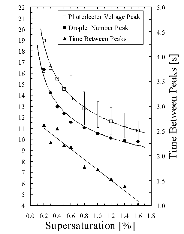
Discussion of the CCN counter’s
calibration dependence on supersaturation (Figure
3).
The condensation
growth rate of droplets is proportional to supersaturation; therefore, at
higher supersaturations droplets will obtain sizes large enough to fall in a
shorter amount of time. This is
confirmed by observations of droplets within our thermal-gradient diffusion
chamber. Changes in droplet size will
affect the calibration slope since the amount of scattered laser light is
proportional not only to droplet number but also to droplet size. Figure 3
illustrates the dependence of the calibration slope on supersaturation, which
is fitted following the method of de Oliveira and Vali (1995). The increase in the calibration slope as the
supersaturation decrease indicates that droplets decrease in size as the
supersaturation decreases and that the effect of this decrease on scattering is
not linear.
Give example for the average ratio
of photodector voltage to maximum photodector voltage for 1.0 and 0.3 %
supersaturation (Figure 4).
The droplet size
dependence on supersaturation is apparent in the time dependence of the ratio
of droplet number, or photodetector voltage, to the maximum droplet number, or
photodetector voltage. Figure 4
shows averages of these ratios over hundreds of samples as the CCN counter’s
chamber is flushed (first 5 s) and droplets activate, grow, and fall out. Ratio averages never equal one since the
peak ratio does not always occur at the same time for each sample. The peak in droplet number (solid lines)
occurs before the peak in photodetector voltage (dashed lines). This indicates that droplets continue to
grow larger, and hence scatter more light, after the occurrence of the droplet
number peak. Averages of the ratios at
1% supersaturation, compared to 0.3% supersaturation, have peaks that occur
earlier in the measurement cycle and are narrower by a factor of 2. This difference is due to the droplet size
dependence on supersaturation that results from the supersaturation dependence
of the condensation growth rate of droplets.
Broad peaks in the averages of the ratios of the droplet number indicate
that it does not make a significant difference exactly where the count of the
droplet number peak is obtained, however, with narrow peaks in the droplet
number it may be more important. This
may be the reason that in Fig. 3
the data points, when compared to the data fit, show a slight (approximately
5%) under counting at high supersaturations and a slight (approximately 5%)
over counting at lower supersaturations.
Talk about how the time to the peak
changes with supersaturation (Figure 5). Talk about how the time between number and
voltage peak changes with supersaturation (Figure
Error! Bookmark not
defined.).
Figure 5
illustrates the time required to reach the droplet number and photodetector
voltage peaks as a function of supersaturation. The standard deviation of the average time to reach the
photodetector voltage peak increases with decreasing supersaturation. The increase in the variability in time to
reach the peaks is due to broader peaks at lower supersaturation (Fig. 4). The time between the average droplet number
peak and the average photodetector voltage peak decreases linearly from 2.5 s
at 0.3 % supersaturation to 1.0 s at 1.6% supersaturation (Fig. 5). This further illustrates the dependence of
condensation growth rate on supersaturation.
Droplets grow more quickly at higher supersaturations reducing the time
between the droplet number and photodetector voltage peak.
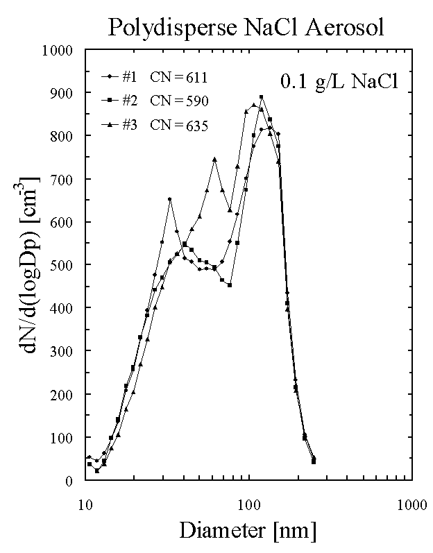
Talk about the aerosol size spectrum
that we use to calibrate the instrument (Figure
6).
The size distribution and chemical composition of atmospheric
aerosols is highly variable in space and time due to the complex
interrelationships between many different sources and sinks (Singh, 1995). Although the laboratory-generated
calibration aerosol has a bimodal, polydisperse size spectrum, it consists of
totally soluble aerosols, and the size distribution does not vary significantly
from sample to sample. Thus, the
calibration aerosols are different from ambient atmospheric aerosols. Figure 6 presents representative aerosol
size spectra for the NaCl laboratory-generated aerosols produced with the
vaporizer. The aerosol spectra are
obtained using a TSI differential mobility analyzer and CN counter (Birmili et
al., 1997).
Describe the systematic variability
in the CCN counter’s calibration (Table 1).
To determine how the laboratory calibration is related to field
measurements, the CCN counter was calibrated using different aerosol types. Table 1
summarizes several different calibrations of the CCN counter. The first three rows give the calibration
results for three calibrations using the standard polydisperse NaCl
aerosol. Row one results are from March
1998, row two results are from June 1998, and row results are three from
October 1998. No changes in the
configuration of the CCN counter were made between these calibrations; however,
the CCN counter was removed from the laboratory calibration bench between each
of these calibrations and used elsewhere.
The random errors of the calculated calibration slopes are given by the
standard deviations in Columns 2 and 3.
The change in the calibration slopes (Column 2 and 3) for the standard
calibration method (Rows 1-3) is larger than the random errors for any one
calibration. Systematic differences in
the setup and alignment of the CCN counter with the video calibration system
are believed to cause the variability between calibrations. The observed variability in the standard
calibration method (Rows 1-3) indicates that the calibration is repeatable to
within 10%.
Calibration dependence on aerosol size.
Roberts et al. (1997)
observed a photodetector calibration dependence on the initial size of CCN in a
static thermal-gradient diffusion chamber.
To check for a calibration dependence on CCN size, the instrument was
calibrated using monodisperse aerosol of several different sizes. The generation and sampling of monodisperse
aerosol was described earlier. Results
of calibrations on different monodisperse aerosol sizes are given in Rows 4-9
of Table 1. Aerosol size appears to have no detectable
effect on the time to reach either the droplet number peak or the photodetector
voltage peak (Columns 4 and 5); however, an approximate 10% change in the calibration
slope is observed between 35 nm and 120/160 nm NaCl aerosol. Further analysis of the measurements shows
that there is no dependence between the time to reach the peaks and the aerosol
concentration.
Discussion of the observed calibration dependence
on aerosol size.
The calibration slope dependence on aerosol size indicates that
the CCN size affects droplet size at the time of the photodetector voltage
peak. This droplet size dependence on
initial CCN size is not intuitive.
Droplets are a few micrometers in diameter at the photodetector voltage
peak based on their fall velocities.
Since the diffusional droplet growth rate is proportional to the inverse
of droplet radius, the droplet size spectrum becomes narrower as droplets grow
to larger sizes (Howell, 1949). Intuitively, the narrowing of the droplet
spectrum is expected to cause the droplets to be at approximately the same
relative size at the photodetector voltage peak. Therefore, the calibration should not depend on the initial CCN
size.
Show the CCN counter calibration on outside
aerosol (Figure 7).
Due to the dependence of the
calibration on CCN size, the calibration may change if we calibrate on
atmospheric aerosol instead of laboratory generated aerosol (Fig. 6). Figure 7
shows calibration data using ambient atmospheric aerosols obtained from outside
the laboratory building on three consecutive mornings in early October at
Laramie, Wyoming. The measurements were
made around sunrise under meteorological conditions of clear skies and high
pressure, similar to a typical balloon flight.
The ambient aerosol concentration was varied by diluting the aerosol
sample with filtered air. Calibration
on outside aerosol does not show a significant difference from the
laboratory-generated NaCl aerosol. The
calibration slope obtained using the outside air is within the range of slopes
obtained for the 3 different calibrations on polydisperse laboratory aerosol
(Table 1,
Rows 1-3). Furthermore, the average
time to reach the peak values (Table 1,
Columns 4 & 5) and shape of the average ratio peaks (not shown) are
consistent with calibration on standard laboratory generated aerosol. The consistency between the calibration on
laboratory-generated aerosol and atmospheric aerosol measured at the surface in
Laramie, Wyoming, suggests that the laboratory calibration can be applied to
field measurements.
It is unknown if atmospheric
aerosols in the upper troposphere or at different geographic locations are
different enough to invalidate the calibration. While it is impossible to check the calibration on all types of
aerosols, the average time to reach the photodetector voltage peak may indicate
measurements that are not consistent with the laboratory calibration. Table 2
gives the time to reach the photodetector voltage peak for various field
measurements. The surface and lower
tropospheric time to reach the photodetector voltage peak are consistent with
the laboratory calibrations (Table 1). The upper tropospheric time to reach the
photodetector voltage peak shows more variability than the laboratory
calibration data, but are still within the range of the laboratory
calibrations. The increase in variability
in the upper troposphere may be related to measurements being near the
detection limit of the CCN counter. The
peak is less well defined near the detection limit since only a few particles
are within the photodetector sample volume.
Talk about the accuracy of the supersaturation
within the thermal gradient diffusion chamber.
Accurate CCN measurements require accurate droplet
concentrations from the scattered light signal and knowledge of the
supersaturation within the thermal-gradient diffusion chamber. The supersaturation within the chamber
depends on the temperature difference between the top and bottom plates. Measurements with a thermocouple placed on
the top and the bottom saturated blotter papers, within the thermal-gradient diffusion
chamber, confirm that the temperature difference is maintained to within ± 0.1 °C or ±
0.05% supersaturation at a supersaturation of 1%. The supersaturation within the diffusion chamber, however, could
be incorrect due to the occurrence of transient supersaturations before
steady-state temperature and moisture gradients are established (Fitzgerald,
1970; Saxena et al., 1970). To avoid
transient supersaturations that exceed the steady-state peak value, it is
advantageous to have air samples enter the diffusion chamber at the top plate
temperature with a low relative humidity (Fitzgerald, 1970; Saxena et al.,
1970). The balloon-borne CCN counter’s
top plate temperature is allowed to float with the instrument enclosure
temperature. Before an air sample
enters the chamber, it travels though 5 mm, inside diameter, stainless steel
tubing within the instrument enclosure for approximately 0.3 s. Heat transfer calculations show that the air
sample equilibrates with the enclosure temperature of the CCN counter before
entering the chamber. Heat produced by
the electronics ensures that the enclosure temperature is higher (from
approximately 3 °C at the surface to 30 °C or
more in the upper troposphere) than the ambient air temperature. Therefore, air entering at the enclosure
temperature of the CCN counter also ensures that the relative humidity of the
air sample is lower than the ambient relative humidity. Since air samples enter the CCN chamber at
the enclosure temperature, transient supersaturations above the steady-state
peak values are believed not to occur within the chamber under field
measurement conditions.
Poisson counting error. Error due to
not knowing the initial aerosol size.
The relative error in CCN concentration can be computed using
Poisson counting statistics (Horvath et al.,
1990). The Poisson counting error can
be significant at upper tropospheric concentrations since there are very few
particles present in the laser beam.
The counting error is larger for video counting of droplets than for
photodetector counting of droplets due to the photodetector sample volume being
approximately twice the video sample volume.
The photodetector sample volume of 0.16 cm-3 determined by
Delene et al (1998) was verified using measurements collected during laboratory
calibrations on monodisperse aerosols.
The Poisson counting error agrees with the standard deviation of 10 min
averages of CCN concentration. Poisson
counting statistics give a range of errors from 36 to 11% for CCN
concentrations (at ambient pressure) of 50 to 500 cm-3. The measurement threshold is approximately
20 cm-3, which corresponds to 3 droplets being within the
photodetector sample volume. Below this
concentration, the photodetector peak is not discernible from the base line
photodetector voltage determined during the chamber flush at the beginning of
the sample.
The agreement between the CCN counter and a laboratory standard,
commercially built TSI CN counter seen in Fig. 2 indicates a good absolute
calibration of the CCN counter. It also
indicates that the video sample volume is correct, and the video camera/lens
system is adequate to calibrate the CCN counter at 1% supersaturation. The variability, approximately 5-10%,
between standard calibrations of the CCN counter (Table 1, Rows 1-3) is thought
to result from systematic differences in the setup and alignment of the CCN
counter with the video calibration system.
Counting droplets using the photodetector to measure the scatter light
signal, instead of counting droplets with a video camera system, has a small
dependence on aerosol size. This size
dependence is approximately the same as the systematic error in the standard
laboratory calibration. The calibration
dependence on aerosol size does not seem to have a great affect in the real
atmosphere since calibration on real atmospheric aerosol produces a calibration
similar to the standard laboratory calibrations.
Considering all calibration results presented here, the
calibration constant relating photodetector voltage to CCN concentration for
the standard laboratory calibration of the balloon-borne CCN counter is
believed to have an accuracy of 10% at 1% supersaturation. The video calibration of the CCN counter
appears to work at supersaturations down to 0.2%. The calibration slopes fit nicely to a power law function (Fig. 3);
however, video counting of droplets is difficult at low supersaturation, due to
the smaller droplets, and the dependence of the calibration constant on aerosol
size may be more significant at supersaturations lower than at 1%. The video calibration method should be
verified at low supersaturations.
A photometric CCN counter was calibrated using a video camera and
PC frame grabber card to count droplets.
Droplet number is linearly related to the amount of laser light
scattered by the droplets. The standard
calibration procedure for the CCN counter is repeatable to better than 10%
accuracy. The calibration relationship
between droplet number and photodetector voltage was verified by a comparison
between the CCN counter and a CN counter when sampling monodisperse
aerosol. Calibration of the CCN counter
is found to depend on supersaturation and to have a slight dependence on the
size of CCN that activate to form droplets.
The dependence on supersaturation is easily accounted for using a power
law function to relate the calibration slope to supersaturation. The calibration dependence on CCN size is
less than 10% at 1% supersaturation.
Calibration on ambient atmospheric aerosol appears similar to the
standard calibration procedure.
Laboratory calibration measurements, compared to field measurements at
various locations and within different atmospheric layers, give average
photodetector voltage peaks that occur at similar times after an air sample
enters the thermal gradient-diffusion chamber.
Therefore, it appears that within the diffusion chamber atmospheric CCN
behave similar to laboratory produced CCN.
Random errors in measured CCN concentration can be computed using
Poisson counting statistics and range from 36 to 11% for CCN concentrations in
the range of 50 to 500 cm-3.
The calibration constant that relates photodetector voltage to CCN
concentration is believed to have an accuracy of 10% at 1% supersaturation.
Lyle Womack and Jason Gonzales provided engineering support in
conducting balloon flights and assistance in laboratory work. Special thanks to Fred Brechtel of Colorado
State University for sharing his computer programs to obtain aerosol size
spectrums and CN concentrations. Fred
Brechtel also provided advice in using the differential mobility analyzer to
generate monodisperse aerosols. Greg
Roberts profiled a copy of his AAAR poster and valuable discussions about his
experience in calibrating a photometric CCN counter. Jefferson Snider, Perry Wechsler, and Gabor Vali provided
support, suggestion, and comments during this research. This research was supported by a grant from
the National Aeronautics and Space Administration.
Bartlett, B. M., and G. P. Ayers, 1981:
Static diffusion cloud chamber. J. Rech.
Atmos., 15, 231-233.
Birmili, W., F. Stratmann, A. Wiedensohler,
D. Covert, L. M. Russell, and O. Berg, 1997: Determination of differential
mobility analyzer transfer functions using identical instruments in series. Aerosol Sci. Technol., 27, 215-223.
Boucher, O., and U. Lohmann, 1995: The
sulfate-CCN-cloud albedo effect: A sensitivity study with two general circulation
models. Tellus, 47B, 281-300.
Chuang, C. C., J. E. Penner, K. E. Taylor,
A. S. Grossman, and J. J. Walton, 1997: An assessment of the radiative effects
of anthropogenic sulfate. J. Geophys. Res.,
102, 3761-3778.
Delene, D. J., T. Deshler, P. Wechsler, and
G. Vali, 1998: A balloon-borne cloud condensation nuclei counter. J. Geophys. Res., 103, 8927-8934.
de Oliveira, J. C. P. and G. Vali, 1995:
Calibration of a photoelectric cloud condensation nucleus counter. Atmos. Res., 38, 237-248.
Fitzgerald, J. W., 1970: Non-steady-state
supersaturations in thermal diffusion chambers. J. Atmos. Sci., 27,
70-72.
Hoppel, W. A., and T. A. Wojciechowski,
1981: Description and discussion of the NRL TGDCC. J. Rech. Atmos., 15,
209-213.
Horvath, H., R. L. Gunter, and S. W.
Wilkison, 1990: Determination of the coarse mode of the atmospheric aerosol
using data from a forward-scattering spectrometer probe. Aerosol Sci. Tech., 12,
964-980.
Howell W. E., 1949: The growth of cloud
drops in uniformly cooled air. J. Meteor.,
6, 134-149.
Katz, J. L., and P. Mirabel, 1975:
Calculation of supersaturation profiles in thermal diffusion cloud chambers. J. Atmos. Sci., 32, 646-652.
Knutson, E. O. and K. T. Whitby, 1975:
Aerosol classification by electric mobility: Apparatus, theory, and
applications. J. Aerosol Sci., 6, 443-451.
Lala, G. G., and J. E. Jiusto, 1977: An
automatic light scattering CCN counter. J.
Appl. Meteorol., 16, 413-418.
Lala, G. G., 1981: An automatic light
scattering CCN counter. J. Rech. Atmos.,
15, 259-262.
Liu, P. S. K., W. R. Leaitch, C. M. Banic,
and S. M. Li, 1996: Aerosol observations at Chebogue Point during the 1993
North Atlantic Regional Experiment: Relationships among cloud condensation
nuclei, size distribution, and chemistry. J.
Geophys. Res., 101, 28,971-28,990.
Meehl, G. A., W. M. Washington, D. J.
Erickson III, B. P. Briegleb, and P. J. Jaumann, 1996: Climate change from
increased CO2 and direct and indirect effects of sulfate aerosols. Geophys, Res. Lett., 23, 3755-3758.
Mertes, S., Schroder, F., and Wiedensohler,
A 1995: The particle detection efficiency curve of the TSI-3010 CPC as a
function of the temperature difference between saturator and condenser, Aerosol Sci. Technol., 23, 257-261.
Pan, W., M. A. Tatang, G. J. McRae, and R.
G. Prinn, 1998: Uncertainty analysis of indirect radiative forcing by
anthropogenic sulfate aerosols. J.
Geophys. Res., 103, 3815-3823.
Radke L. F. and P. V. Hobbs, 1969: An
automatic cloud condensation nuclei counter. J. Appl. Meteorol., 8,
105-109.
Roberts G, R. Flagan, G. Lala, and M.
Andreae, 1997: Photodetector output calibration of a photometric static
thermal-gradient cloud condensation nuclei counter, paper presented at 16th
Annual Conference of the American Association for Aerosol Research, Denver,
Colorado.
Saxena, V. K., J. N. Burford, and J. L.
Kassner, Jr., 1970: Operation of a thermal diffusion chamber for measurements
on cloud condensation nuclei. J. Atmos.
Sci., 27, 73-80.
Singh, H. B., 1995: Atmospheric aerosols. Composition, Chemistry, and Climate of the Atmosphere.
Van Nostrand Reinhold, New York, pp. 120-175.
Twomey, S., Aerosols, 1991: Clouds and
Radiation, Atmos. Environ., 25A, 2435-2442.
Wigley, T. M. L., 1989: Possible climate
change due to SO2-Derived cloud condensation nuclei. Nature, 339, 365-367.
Willeke K., and P. A. Baron, 1993: Aerosol Measurement: Principles, Techniques,
and Applications, Van Nostrand Reinhold, New York, pp. 48-49.
10. Figure Captions
Figure 1. The photodetector voltage peak versus the number of droplets
counted within the video sample volume and the corresponding droplet
concentration. Droplets are counted at
the time of the photodetector voltage peak.
The droplets nucleated on polydisperse NaCl aerosols produced using a
solution of 0.1 g/L of NaCl in an ultrasonic vaporizer. The calibration slope (solid line) is the
least squares linear fit to the data with a forced zero y-intercept.
Figure 2. Measurements of the concentration of 120 nm monodisperse NaCl
aerosols using the CCN counter at 1% supersaturation (circles) and CN counter
(solid line). The CCN concentration is
measured using the video camera to count droplets over a predetermined video
sample volume. The CCN concentration is
averaged over approximately 20 samples (10 min) with the standard deviation
given by the error bars. The decrease
in concentration with time is the result of aerosol being removed to the walls
of the sampling bag. Filtered air was
continuously added to the sampling bag after 115 minutes
Figure 3. The CCN counter’s calibration slope dependence on
supersaturation. The data are fitted
using the equation, C = Alpha + Beta/SS, where Alpha and Beta are calibration
constants, SS is the chamber supersaturation, and C is the calibration
slope. Error bars represent one
standard deviation in the calculated calibration slope.
Figure 4. Time versus the averages of ratios of droplet number (dashed
line) and photodetector voltage (solid line) to the maximum number and voltage
observed during the sample. The legends
give the average and standard deviation times for the peak number of droplets
and peak photodetector voltage. Time
zero is at the beginning of a 5 s chamber flush. Following the chamber flush, an air sample is captured within the
chamber, CCN active and droplets form, grow and begin to fall.
Figure 5. Supersaturation of the CCN counter versus the average time to
reach the number or voltage peak. The
error bars on the photodetector voltage time are one standard deviation of the
average. Error bars (not shown) on the
average time to reach the droplet number peak are similar. The left axis and solid triangles denote the
time between the droplet number peak and photodetector voltage peak.
Figure 6. Examples of the aerosol size
spectrum generated using a solution of 0.1 g/L of NaCl in an ultrasonic
vaporizer. The legend gives the total
number concentration (in cm-3) for each aerosol size spectrum.
Figure 7. CCN counter calibration data using aerosol from the ambient
atmosphere outside the laboratory building in Laramie, Wyoming. The
photodetector voltage peak versus the number of droplets counted within the
video sample volume and the corresponding droplet concentration are shown. Droplets are counted at the time of the
photodetector voltage peak. The calibration
slope (solid line) is the least squares linear fit to the data with a forced
zero y-intercept.
11. Table Captions
Table
1. Calibration of the balloon-borne
CCN counter at 1% supersaturation. The
first column gives the calibration aerosol type: laboratory produced aerosol
using a solution of 0.1 g/L NaCl in a vaporizer, monodisperse NaCl aerosol of
different diameters, or aerosol from the ambient atmosphere outside the
laboratory building. The second column
gives the calibration slope using the photodetector voltage peak. The third column gives the calibration slope
using a three-point sum around the photodetector voltage peak (Delene et al., 1998). The fourth column gives the average time to reach the number peak
in seconds since the beginning of the sample.
The last column gives the average time to reach the voltage peak in
seconds since the beginning of the sample.
The first 3 rows give the results of the standard calibration of the CCN
counter in March, June, and, October 1998.
The CCN counter was removed from the laboratory calibration bench
between each standard calibration of the CCN counter and used elsewhere. The calibrations
presented
in rows 3-10 were preformed using the same focus and video camera alignment
with the CCN counter.
Table 2. Time to reach the photodetector volage peak for field
measurements in Laramie, Wyoming (41 °N), Lauder, New Zealand
(45 °S),
and Fairbanks, Alaska (65 °N). Due to a
clear difference in aerosol concentration, the field measurements are divided
into summer and winter seasons. The
third column gives the average and standard deviation of the time to reach the photodetector voltage peak. The fourth column gives the number of
samples used to compute the average.